Here is an inexpensive way to get slow-moving analog data directly into a spreadsheet on your computer! A simple circuit connects to a serial port and a short Qbasic program gathers and saves 12 bit data to a file. A spreadsheet automatically retrieves the file and displays the data in real time. Once the data is in the spreadsheet, the full power and flexibility of the office suite is available.
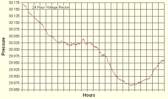
All of the software is free and the hardware is inexpensive! This simple interface can be built right into your project, turning it into a computer peripheral device. As an example, the chart below is a plot of the barometric pressure in Austin over a 24 hour period recorded using this data converter reading an electronic barometer. This chart was created automatically in real time:

That is a pretty nice chart for a system consisting of free software and about $15 worth of parts!
You will need a spreadsheet program to display the data, a program to read data from the data taker and the data taker itself.
The recommended spreadsheet program is part of the free office suite from www.openoffice.org (or buy an enhanced version of the suite from Sun at http://wwws.sun.com/software/star/staroffice/6.0/index.html ). It has the required ability to import and automatically update HTML table data:
Here is how to make your own spreadsheet using openoffice.org that imports data from a table on a web page or html file: Select a cell where you want the data to start and select 'External Data' from the 'Insert' menu. Enter your file path or browse to find it, select "HTML_tables", and set the update rate (I use 60 seconds for the barometer). As long as the file contains something that looks like an HTML table, everything will work fine! The Qbasic program will create a file with the right format. (If you don't see "HTML_tables" or the "OK" button is grayed out, your file does not look like an HTML table.) The power of this feature boggles the mind!
A new Qbasic program interfaces to the data taker. It reads the voltage via a serial port and saves the data to a file in the form of an HTML single column table. Run qbasic.exe to start basic then run the data taking program from within qbasic. Ah, the good old days!
Note: In order to run or edit the basic program, qbasic.exe is required but your machine may not have it installed. If not, you will need to copy it from your Windows install disk. Look for qbasic.exe in a directory with a name like "oldmsdos" and drag it into a folder on your hard drive. GWbasic may work also. You are probably out of luck on operating systems beyond Windows 98. Windows XP doesn't allow such simple communications with the serial port, as far as I know.
Two spreadsheets and the older qbasic program are in a zipped file. You may wish to replace the Qbasic program in that zipped file with a new basic program that makes three files, a 60 minute file, a 24 hour file and a 60 day file. The 60 minute and 24 hour files begin "rolling" once they are full, showing the latest data only (60 points and 24 points, respectively). The three files are much smaller and are easier for the spreadsheet program to handle. This program attempts to automatically set the data conversion speed to 20 seconds and it lets the user select options like com port and calibration coefficients. It also has a few more messages on the screen to let you know what is going on. Make your own spreadsheet using the external data input as with the other program but remember you can't import the data if the file doesn't exist yet (one full day for all three files to appear). Nothing bad happens, just no data appears. For those of you that are using the data taker for other purposes, this program is a good starting point and is easily modified.
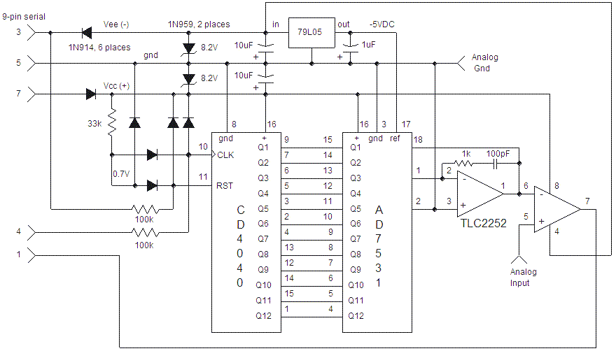
The interface is pretty simple:


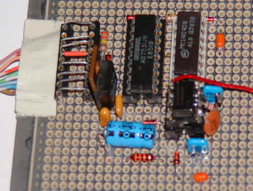
The jumper arrangement in the prototype allowed for easy testing and may be left out. Sockets were used to simplify experimentation.
In order to avoid using a power supply, power for the circuit is extracted from two of the three outputs on the serial port. One output is set high for the positive voltage (pin 7) and one is set low for the negative voltage (pin 3) by the qbasic program. Two zener diodes are connected from these lines to ground (pin 5) to limit the voltage to about 8 volts to protect the op-amp. The zeners would not be needed if a higher voltage op-amp were substituted as long as it is a micropower device; not much power is available from the serial port outputs. A handful of diodes and three resistors clamp the input voltages to acceptable levels. A CD4040 12 bit counter (Not CD74HC4040!) drives a 12 bit digital-to-analog converter (AD7521,31,or 41) and a low power dual CMOS op-amp compares the output of the D/A to an analog input voltage. The basic program simply advances the counter until the D/A output exceeds the analog input and records the count when it happens. The counting process continues to the end so that each conversion takes the same length of time regardless of the input voltage.
Notice that pin 1 of the op-amp could be used to output an analog voltage. Setting the output is slow since the voltage must be ramped up from zero but for some applications it is perfect. For example, the voltage could control the setpoint of a temperature chamber that slowly ramps between two limits or the speed of a motor or the brightness of a lamp.
Notes:
| Reset is accomplished by briefly raising the pin providing the negative supply voltage (pin 3); a 10uF capacitor provides the required negative voltage for this brief period. Using a larger capacitor might be a good idea in case the computer is on the slow side. | |
| The reference voltage for the D/A comes from a negative voltage regulator. The 79L05 is not a precision device and it does drift a bit with temperature changes but for most measurement applications the stability is fine. For more precision use the AD7541 and a better negative voltage reference device (micropower, of course). |
Once you see how easy it is to use the serial port, other ideas will come to mind:
| An external power supply will free up all three output bits allowing the counter above to be replaced with a shift register for faster "successive approximation" conversions or a "tracking" converter. | |
| The three output bits could control a data multiplexer to multiplex in 8, 4-bit BCD digits from a frequency counter, two 4 digit meters, or other BCD sources. | |
| A low frequency (or divided down) V/F converter could be counted for a time determined by an externally generated clock, perhaps a 10 second gate produced by dividing down a crystal oscillator. The resolution could be fantastic and the V/F is perfect for integration. Don't bother trying to use the computer's internal clock for timing from a Qbasic program - there is just too much variation. But the computer can respond to an accurate external gate quite rapidly! | |
| The spreadsheet can be programmed to periodically save in HTML format to a web server! (see 'options - load/save - general') So your web page could have real-time plots of weather data, background radioactivity, or whatever you dream up. I have not tried this feature and I didn't see a way to set permissions; maybe a password window pops up. I can't imagine an easier way to do some pretty cool live content web pages! | |
| Instead of the spreadsheet importing table data created by a basic program, it could import table data from a server on the Internet, perhaps a table you can control remotely. The contents of the table would be automatically saved by the spreadsheet program and then used by a basic program to control external devices. A professional programmer would probably laugh but it sure would be easy! The spreadsheet and basic program bridge the gap between the internet and your little circuit creation without mind-bending software issues. |
Here is how the hardware works:
The serial port (com port) on your computer may be used as an abbreviated parallel port with three pins dedicated to output (pins 3,4 and 7) and four pins to input (pins 1,6,8 and 9). Pin 5 is ground and pin 2 is a serial pin that is not used. These pins are bipolar in nature, with current-limited swings as high as +-12 volts with the negative voltage indicating a logic low. Each com port has an 8 byte Input/Output address range that may be determined by looking at the properties of the com port under the system properties tab of the control panel. Com1 data range is 03F8 to 03FF, for example:
| Bit Values | 128 - 64 - 32 - 16 - 8 - 4 - 2 - 1 |
| 03F8 | 03F9 | 03FA | 03FB | 03FC | 03FD | 03FE | 03FF |
| x x x x x x x x | x x x x x x x x | x x x x x x x x | x 3 x x x x x x | x x x x x x 7 4 | x x x x x x x x | 1 9 6 8 x x x x | x x x x x x x x |
We are only interested in 7 of the bits (in red); the bits for the three output pins and four input pins. The red numbers in the above chart represent the serial port 9-pin connector pin numbers. The data in the '64' bit of 03FB sets pin 3, the '1' and '2' bit of 03FC set pins 4 and 7, and the four MSBs of 03FE contain the four inputs from pins 8,6,9 and 1. Using the outputs is quite simple: set an output bit high and the pin goes high. Just read the four input bits to directly determine the logic levels on the input pins. A simple way to get access to these registers is to use the IN and OUT commands in Qbasic. Just remember that each bit has a value determined by its position in the byte. For example, to set pin 3 high, you would output a 64 to 03FB and to read pin 6 you would look for a 32 in the hex value in 03FE ( '32 AND 03FE' will evaluate as either 32 or 0 depending on whether that bit is a 1 or 0). You could set both pins 4 and 7 high by outputting a 3 into 03FC since 3 is '11' in binary. The output bytes may be read back with the IN command to verify that the output data is correct.
No comments:
Post a Comment