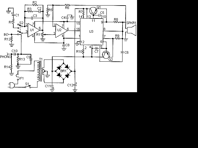
| Part | Total Qty. | Description | Substitutions |
| R1 | 1 | 200 Ohm 1/4 W Resistor | |
| R2 | 1 | 200K 1/4 W Resistor | |
| R3 | 1 | 30K 1/4 W Resistor | |
| R5 | 1 | 1K 1/4 W Resistor | |
| R6 | 1 | 5K 1/4 W Resistor | |
| R7,R10 | 2 | 1 Meg (5%) 1/2 W Resistor | |
| R8,R9 | 2 | 0.4 Ohm 5 W Resistor | |
| R11 | 1 | 10K Pot | |
| R12,R13 | 2 | 51K 1/4 W Resistor | |
| R14 | 1 | 47K 1/4 W Resistor | |
| C1 | 1 | 100uF 35V Electrolytic Capacitor | |
| C2 | 1 | 0.011uF Capacitor | |
| C3 | 1 | 3750pF Capacitor | |
| C4,C6 | 2 | 1000pF Capacitor | |
| C5,C7,C8 | 3 | 0.001uF Capacitor | |
| C9 | 1 | 50pF Capacitor | |
| C10 | 1 | 0.3uF Capacitor | |
| C11,C12 | 2 | 10,000uF 50V Electrolytic Capacitor | |
| U1,U2 | 2 | 741 Op Amp | |
| U3 | 1 | ICL8063 Audio Amp Transister Driver thingy | |
| Q1 | 1 | 2N3055 NPN Power Transistor | |
| Q2 | 1 | 2N3791 PNP Power Transistor | |
| BR1 | 1 | 250 V 6 Amp Bridge Rectifier | |
| T1 | 1 | 50V Center Tapped 5 Amp Transformer | |
| S1 | 1 | SPST 3 Amp Switch | |
| S2 | 1 | DPDT Switch | |
| F1 | 1 | 2 Amp Fuse | |
| SPKR1 | 1 | 8 Ohm 50W Speaker | |
| MISC | 1 | Case, Knobs, Line Cord, Binding Posts Or Phono Plugs (For Input And Output), Heatsinks For Q1 And Q2 | |
| |

No comments:
Post a Comment